VNC Server setup guide for Ubuntu

Usually, I used Fedora/CentOS as the development system. Recently, as I move into the machine learning world, I get my laptop setup with Ubuntu 14.04 LTS to utilize my GTX 860M for running ML algorithms. However, to set up vncserver properly on Ubuntu does not seems to be as easy as on Fedora/CentOS. In a lot of cases, you end up getting a blank desktop in your vnc-client with no menu and a basic GTK looking terminal.

I have searched online quite some while ago to find a good and easy way of setting up the vnc server and here comes the resolution. I cannot find the original post for the same method, so if you know, please give me a feedback there that I can credit the original writer.

1. Use x11vnc instead of tigervnc

To my knowledge, if you use tigervnc (command vncserver) as your vncserver, you are likely end up with a blank screen on your vnc-client. You need to add several parameters to your ~/.vnc/xstartup to start the old 2d unity menus and get it functional.

However, it seems to be pretty to setup with x11vnc without any change to xstartup script – and here is how:

Install x11vnc with command

$ apt-get install x11vnc

or you can download the newest x11vnc from sourceforge:


$ sudo apt-get install checkinstall
$ wget http://x11vnc.sourceforge.net/dev/x11vnc-0.9.14-dev.tar.gz
$ gzip -dc x11vnc-0.9.14-dev.tar.gz | tar -xvf -
$ cd x11vnc-0.9.14/
$ ./configure
$ make
$ sudo checkinstall --pkgname=x11vnc --default --pkgversion="2:0.9.14-0.1" --backup=no --deldoc=yes

Create authentication password:

$ sudo /usr/local/bin/x11vnc --storepasswd /etc/x11vnc.pass

Start x11vnc with command:

$ sudo /usr/local/bin/x11vnc -auth /var/run/lightdm/root/:0 -display :0 -rfbauth /etc/x11vnc.pass -rfbport 5900 -noxrecord -noxfixes -noxdamage -forever -bg -o /var/log/x11vnc.log

You can figure out the meaning of all those parameters with $ x11vnc -help

To start it automatically, create a file /etc/init/x11vnc.conf

Put following lines in the file


start on login-session-start
script
/usr/local/bin/x11vnc -auth /var/run/lightdm/root/:0 -display :0 -rfbauth /etc/x11vnc.pass -rfbport 5900 -noxrecord -noxfixes -noxdamage -forever -bg -o /var/log/x11vnc.log
end script

2. Repeat Key Fix

The only draw back about x11vnc is the reaction to key repeating when you long pressing the same key on keyboard.
This issue only apply to VNC client in Windows.
And the problem is how VNC client react to key-long pressing in windows and linux

From the server side, you can actually configure it on the fly:

For Windows, if you want to enable key repeating, open a command line and type:
$ x11vnc -R repeat

For Linux, you need to disable repeat option by
$ x11vnc -R norepeat

And now, everything works fantastic!!
Enjoy!

Xilinx Driver Installation in Fedora 19

Pre-requisit Packages

  • GCC Compiler
    You can install with command
    $sudo yum install gcc make
  • libusb development package
    In order to compile usb driver library for Xilinx Tools, libusb development package needed to be installed. It can be installed via command
    $sudo yum install libusb libusb-devel
  • fxload package
    fxload package can be installed via command
    $sudo yum install fxload
  • git
    git is used to download libusb-driver source code from a public git repository. git can be installed via command
    $sudo yum install git

Install pcusb driver

In this blog, Xilinx 14.6 is used as an example. In Xilinx 14.6 package, the pcusb installation script has not been updated to work with 3.x kernels. So, we need to modify install pcusb installation script a bit to use udev no matter what.

Open pcusb setup script “setup_pcusb” under <Xilinx_ISE_DS_DIR>/ISE/bin/lin64/install_script/install_drivers/linux_drivers/pcusb
[tinghui.wang@localhost ~]$cd /opt/Xilinx/14.6/ISE_DS/ISE/bin/lin64/install_script/install_drivers/
linux_drivers/pcusb/

[tinghui.wang@localhost pcusb]$ sudo vim setup_pcusb
[sudo] password for tinghui.wang:

Assign TP_USE_UDEV to 1 by inserting TP_USE_UDEV="1" after kernel version checking as follows:
45 else
46 TP_USE_UDEV=$1
47 fi;
48
49 TP_USE_UDEV="1"
50
51 if [ $TP_USE_UDEV = "1" ]
52 then
53 echo "--Using udev..."
54 fi;

Then install pcusb driver by typing following in the terminal:
[tinghui.wang@localhost pcusb]$ sudo ./setup_pcusb
--Using udev...
--File /usr/share/xusbdfwu.hex does not exist.
--File version of /usr/share/xusbdfwu.hex = 1030
--Updating xusbdfwu.hex file.
--File /usr/share/xusb_xlp.hex does not exist.
--File version of /usr/share/xusb_xlp.hex = 0000.
--Updating xusb_xlp.hex file.
--File /usr/share/xusb_emb.hex does not exist.
--File version of /usr/share/xusb_emb.hex = 0000.
--Updating xusb_emb.hex file.
--File /usr/share/xusb_xpr.hex does not exist.
--File version of /usr/share/xusb_xpr.hex = 0000.
--Updating xusb_xpr.hex file.
--File /usr/share/xusb_xup.hex does not exist.
--File version of /usr/share/xusb_xup.hex = 0000.
--Updating xusb_xup.hex file.
--File /usr/share/xusb_xp2.hex does not exist.
--File version of /usr/share/xusb_xp2.hex = 0000.
--Updating xusb_xp2.hex file.
--File /usr/share/xusb_xse.hex does not exist.
--File version of /usr/share/xusb_xse.hex = 0000.
--Updating xusb_xse.hex file.
--File /etc/udev/rules.d/xusbdfwu.rules does not exist.
--File version of /etc/udev/rules.d/xusbdfwu.rules = 0000.
--Updating rules file.

Install Digilent Driver Files

To let Xilinx iMPACT work with Digilent boards, we need to install Digilent plugin. Digilent plugin comes with Xilinx Design Suite, located at <Xilinx_ISE_Suite>/ISE/bin/lin64/digilent/
[tinghui.wang@localhost ~]$ cd /opt/Xilinx/14.6/ISE_DS/ISE/bin/lin64/digilent/
[tinghui.wang@localhost digilent]$ sudo ./install_digilent.sh

Modify Udev Rules

In Fedora 19, the syntax for udev rules has been updated. So, we need to modify the rule files as well. Here is the /etc/udev/rules.d/xusbdfwu.rules
1 # version 0003
2 ATTRS{idVendor}=="03fd", ATTRS{idProduct}=="0008", MODE="666"
3 SUBSYSTEMS=="usb", ACTION=="add", ATTRS{idVendor}=="03fd", ATTRS{idProduct}=="0007", RUN+="/sbin/fxload -v -t fx2 -I /usr/share/xusbdfwu.hex -D $tempnode"
4 SUBSYSTEMS=="usb", ACTION=="add", ATTRS{idVendor}=="03fd", ATTRS{idProduct}=="0009", RUN+="/sbin/fxload -v -t fx2 -I /usr/share/xusb_xup.hex -D $tempnode"
5 SUBSYSTEMS=="usb", ACTION=="add", ATTRS{idVendor}=="03fd", ATTRS{idProduct}=="000d", RUN+="/sbin/fxload -v -t fx2 -I /usr/share/xusb_emb.hex -D $tempnode"
6 SUBSYSTEMS=="usb", ACTION=="add", ATTRS{idVendor}=="03fd", ATTRS{idProduct}=="000f", RUN+="/sbin/fxload -v -t fx2 -I /usr/share/xusb_xlp.hex -D $tempnode"
7 SUBSYSTEMS=="usb", ACTION=="add", ATTRS{idVendor}=="03fd", ATTRS{idProduct}=="0013", RUN+="/sbin/fxload -v -t fx2 -I /usr/share/xusb_xp2.hex -D $tempnode"
8 SUBSYSTEMS=="usb", ACTION=="add", ATTRS{idVendor}=="03fd", ATTRS{idProduct}=="0015", RUN+="/sbin/fxload -v -t fx2 -I /usr/share/xusb_xse.hex -D $tempnode"

In /etc/udev/rules.d/52-digilent-usb.rules, 38 ATTRS{idVendor}=="1443", MODE:="666" 39 ACTION=="add", ATTRS{idVendor}=="0403", ATTRS{manufacturer}=="Digilent", MODE="666", RUN+="/usr/local/sbin/dftdrvdtch %s{busnum} %s{devnum}"
You also need to create a third acl rule file to auto change the mode of the device. The one I created is named
1 ENV{MAJOR}=="", GOTO="acl_end"
2 ENV{ACL_MANAGE}=="0", GOTO="acl_end"
3 ACTION!="add|change", GOTO="acl_apply"
4
5 SUBSYSTEM=="usb", ATTRS{idVendor}=="03fd", ATTR{idProduct}=="0008", ENV{ACL_MANAGE}="1"
6
7 # apply ACL for all locally logged in users
8 LABEL="acl_apply", ENV{ACL_MANAGE}=="1", TEST=="/var/run/ConsoleKit/database", \
9 RUN+="udev-acl --action=$env{ACTION} --device=$env{DEVNAME}"
10
11 LABEL="acl_end"
12 #

Compile libusb-driver.so for Xilinx Tools

Download libusb-driver source files from git://git.zerfleddert.de/usb-driver
[tinghui.wang@localhost Downloads]$ git clone git://git.zerfleddert.de/usb-driver
Cloning into 'usb-driver'...
remote: Counting objects: 751, done.
remote: Compressing objects: 100% (525/525), done.
remote: Total 751 (delta 455), reused 412 (delta 226)
Receiving objects: 100% (751/751), 129.08 KiB | 117.00 KiB/s, done.
Resolving deltas: 100% (455/455), done.

Get into usb-driver folder. Run make to compile libusb-driver.so:
[tinghui.wang@localhost usb-driver]$ make cc -Wall -fPIC -DUSB_DRIVER_VERSION="\"2013-09-10 22:28:10\"" usb-driver.c xpcu.c parport.c config.c jtagmon.c -o libusb-driver.so -ldl -lusb -lpthread -shared parport.c: In function 'parport_transfer': parport.c:21:23: warning: variable 'last_pp_write' set but not used [-Wunused-but-set-variable] static unsigned char last_pp_write = 0; ^ cc -DDEBUG -Wall -fPIC -DUSB_DRIVER_VERSION="\"2013-09-10 22:28:10\"" usb-driver.c xpcu.c parport.c config.c jtagmon.c -o libusb-driver-DEBUG.so -ldl -lusb -lpthread -shared Built library is 64 bit. Run `make lib32' to build a 32 bit version [tinghui.wang@localhost usb-driver]$
Ignore all the warnings, and you will see libusb-driver.so under the folder.

Environment Settings

We need to use libusb-driver.so for iMPACT, so we specify LD_PRELOAD environment variable. You can do this in .bashrc environment setting file or export it before using iMPACT.
export LD_PRELOAD="~/Download/usb-driver/libusb-driver.so"

Run Linaro Ubuntu Desktop on ZED AP SoC Board – Step-By-Step Guide

ZED board is currently shipped with Linux kernel with a RAM disk file systems.
However, it is fairly simple to get a desktop version of Linaro Ubuntu running on it.
In this blog, I will give you step-by-step instructions with pictures to get Linaro Ubuntu running on your ZED board with the kernel image in the SD card.

Things You Need

A. A Linux Machine

You need a Linux machine to format disks, copy files, etc. You cannot do these under Windows because Windows does not support EXT filesystem, and cannot understand special files (e.g. device files, link files, etc.) which only exists for Unix-like systems. Any Linux distributions, such as Fedora, CentOS, RHEL, Ubuntu, ArchLinux, etc.) can satisfy our needs.

B. Linaro Ubuntu File System Image

You can view Linaro Ubuntu as a Ubuntu distribution specifically for ARM-based processors. You can obtained the file system image from linaro 12.09. The file system is about 500ish MB. The current built is called: linaro-precise-ubuntu-desktop-20120923-436.tar.gz

C. SD Card Image (containing Kernel, BOOT.BIN, etc.)

Before we move on to modify the SD card, it is recommended to store the files on the SD card to some place. However, you can also obtain those files from Digilent Website: Out-of-Box SD Card Image .

Idea for Running Desktop

To run desktop linux, you just need to swap the file system from RAMDISK to linaro file system image. The ramdisk gets loaded up into the SDRAM by bootloader, and the memory address is passed to kernel via boot args (defined in device tree file: devicetree_ramdisk.dtb). However, the file system of Ubuntu is above 500MB. So, we cannot load it as the way we deal with RAMDISK (which is usually around 4~8 MB). As a result, we are going to make a second partition on SD card (3GB), make a root filesystem on it, and point it as the root filesystem in dtb file.

Step-by-Step Instructions

A. Repartition the SD Card

1. Plug in your SD Card to your Linux machine. Some distribution will automatically mount the partition on SD Card. So, you need to umount the automounted partitions first, before we repartition the disk.

On my computer, when I insert the SD card, the device node created for the SD card on my machine is /dev/sdd:

[tinghui.wang@DIGILENT_LINUX ~]$ df 
Filesystem 1K-blocks Used Available Use% Mounted on
/dev/mapper/VolGroup-lv_root
470166952 316061992 130221800 71% /
tmpfs 3988440 976 3987464 1% /dev/shm
/dev/sda1 495844 65557 404687 14% /boot
/dev/sdd1 3862528 10268 3852260 1% /media/ZED_BOOT

Umount the pre-mounted SD Card Partition:

[tinghui.wang@DIGILENT_LINUX ~]$ sudo umount /media/ZED_BOOT/
[tinghui.wang@DIGILENT_LINUX ~]$ df
Filesystem 1K-blocks Used Available Use% Mounted on
/dev/mapper/VolGroup-lv_root
470166952 316062016 130221776 71% /
tmpfs 3988440 976 3987464 1% /dev/shm
/dev/sda1 495844 65557 404687 14% /boot
[tinghui.wang@DIGILENT_LINUX ~]$

2. Now we will delete the original 4G FAT Partition and create two partitions: first one is 1GB FAT for booting files, and second one is 3GB EXT4 for root file system. The partition utility we will use is fdisk.

Open the SD card device using fdisk, and use command p to print current partition table on SD card.

[tinghui.wang@DIGILENT_LINUX ~]$ sudo fdisk /dev/sdd
[sudo] password for tinghui.wang:

WARNING: DOS-compatible mode is deprecated. It's strongly recommended to
switch off the mode (command 'c') and change display units to
sectors (command 'u').

Command (m for help): p

Disk /dev/sdd: 3965 MB, 3965190144 bytes
228 heads, 2 sectors/track, 16983 cylinders
Units = cylinders of 456 * 512 = 233472 bytes
Sector size (logical/physical): 512 bytes / 512 bytes
I/O size (minimum/optimal): 512 bytes / 512 bytes
Disk identifier: 0x00047708

Device Boot Start End Blocks Id System
/dev/sdd1 1 16978 3870720 b W95 FAT32

Type command d to delete the partition. As there is only one partition on SD card, it will be deleted automatically.

Command (m for help): d
Selected partition 1

Command (m for help): p

Disk /dev/sdd: 3965 MB, 3965190144 bytes
228 heads, 2 sectors/track, 16983 cylinders
Units = cylinders of 456 * 512 = 233472 bytes
Sector size (logical/physical): 512 bytes / 512 bytes
I/O size (minimum/optimal): 512 bytes / 512 bytes
Disk identifier: 0x00047708

Device Boot Start End Blocks Id System

Now it’s time for us to create new partitions. We will create
a. A primary partition, Partition Number 1, Start from first Cylinder, Size of 1GB;
b. A primary partition, Partition Number 2, Start from next available Cylinder, Take rest of the available space on SD Card.
Command n stands for “New Partitions”.

Command (m for help): n
Command action
e extended
p primary partition (1-4)
p
Partition number (1-4): 1
First cylinder (1-16983, default 1): 1
Last cylinder, +cylinders or +size{K,M,G} (1-16983, default 16983): +1G

Command (m for help): p

Disk /dev/sdd: 3965 MB, 3965190144 bytes
228 heads, 2 sectors/track, 16983 cylinders
Units = cylinders of 456 * 512 = 233472 bytes
Sector size (logical/physical): 512 bytes / 512 bytes
I/O size (minimum/optimal): 512 bytes / 512 bytes
Disk identifier: 0x00047708

Device Boot Start End Blocks Id System
/dev/sdd1 1 4600 1048799 83 Linux

Command (m for help): n
Command action
e extended
p primary partition (1-4)
p
Partition number (1-4): 2
First cylinder (4601-16983, default 4601):
Using default value 4601
Last cylinder, +cylinders or +size{K,M,G} (4601-16983, default 16983):
Using default value 16983

Command (m for help): p

Disk /dev/sdd: 3965 MB, 3965190144 bytes
228 heads, 2 sectors/track, 16983 cylinders
Units = cylinders of 456 * 512 = 233472 bytes
Sector size (logical/physical): 512 bytes / 512 bytes
I/O size (minimum/optimal): 512 bytes / 512 bytes
Disk identifier: 0x00047708

Device Boot Start End Blocks Id System
/dev/sdd1 1 4600 1048799 83 Linux
/dev/sdd2 4601 16983 2823324 83 Linux

So far, we have finished creating two new partitions. We write our changes back to SD card using command w and fdisk will quit automatically after disk is sychronized.

Command (m for help): w
The partition table has been altered!

Calling ioctl() to re-read partition table.
Syncing disks.
[tinghui.wang@DIGILENT_LINUX ~]$
B. Creating File Systems

Next Step is to create file systems. We need to format the first partition to FAT with label “ZED_BOOT”, and Second one EXT4 with label “ROOT_FS”. The utility we use for formatting partitions is makefs.

[tinghui.wang@DIGILENT_LINUX ~]$ sudo mkfs -t vfat -n ZED_BOOT /dev/sdd1
mkfs.vfat 3.0.9 (31 Jan 2010)
[tinghui.wang@DIGILENT_LINUX ~]$ sudo mkfs -t ext4 -L ROOT_FS /dev/sdd2
mke2fs 1.41.12 (17-May-2010)
Filesystem label=ROOT_FS
OS type: Linux
Block size=4096 (log=2)
Fragment size=4096 (log=2)
Stride=0 blocks, Stripe width=0 blocks
176704 inodes, 705831 blocks
35291 blocks (5.00%) reserved for the super user
First data block=0
Maximum filesystem blocks=725614592
22 block groups
32768 blocks per group, 32768 fragments per group
8032 inodes per group
Superblock backups stored on blocks:
32768, 98304, 163840, 229376, 294912

Writing inode tables: done
Creating journal (16384 blocks): done
Writing superblocks and filesystem accounting information: done

This filesystem will be automatically checked every 37 mounts or
180 days, whichever comes first. Use tune2fs -c or -i to override.
[tinghui.wang@DIGILENT_LINUX ~]$

Now, unplug the SD Card from your computer and plug it in again. In most Linux distributions, both partitions will be mounted to /media/ZED_BOOT and /media/ROOT_FS automatically. If not, you need to create two folders manually and mount them manually.

C. Creating Linaro Ubuntu Root Filesystem

Personally, I would like to create a folder named linaro under /tmp and copy the zipped linaro image there.

[tinghui.wang@DIGILENT_LINUX ~]$ mkdir -p /tmp/linaro
[tinghui.wang@DIGILENT_LINUX ~]$ sudo cp /home/tinghui.wang/Downloads/linaro-precise-ubuntu-desktop-20120923-436.tar.gz /tmp/linaro/
[tinghui.wang@DIGILENT_LINUX ~]$ cd /tmp/linaro/
[tinghui.wang@DIGILENT_LINUX linaro]$ ls
32mlinaro-precise-ubuntu-desktop-20120923-436.tar.gz
[tinghui.wang@DIGILENT_LINUX linaro]$

Unpack the disk image using tar. (Part of the log is omitted for brevity).

[tinghui.wang@DIGILENT_LINUX linaro]$ tar zxvf linaro-precise-ubuntu-desktop-20120923-436.tar.gz
binary/
binary/md5sum.txt
binary/boot/
binary/boot/filesystem.dir/
binary/boot/filesystem.dir/.disk/
binary/boot/filesystem.dir/.disk/casper-uuid
binary/boot/filesystem.dir/var/
...
binary/boot/filesystem.dir/srv/
binary/boot/filesystem.dir/opt/
binary/boot/filesystem.dir/media/
binary/boot/filesystem.dir/tmp/
[tinghui.wang@DIGILENT_LINUX linaro]$ ls
binary linaro-precise-ubuntu-desktop-20120923-436.tar.gz

After unpacking the disk image, the root filesystem lies at /tmp/linaro/binary/boot/filesystem.dir. So the next step to do is to copy the root filesystem into the second partition of our SD Card, mounted already to /media/ROOT_FS. A lot of files in the root filesystem are special files with special attributes, I would recommend to use rsync to do the copy, which keeps the attibutes for every file. It takes a while to copy the file to SD card, basically depended on your SD card speed. (Part of the log is omitted for brevity).

[tinghui.wang@DIGILENT_LINUX binary]$ cd binary/boot/filesystem.dir/
[tinghui.wang@DIGILENT_LINUX filesystem.dir]$ pwd
/tmp/linaro/binary/boot/filesystem.dir
[tinghui.wang@DIGILENT_LINUX filesystem.dir]$ sudo rsync -a --progress ./ /media/ROOT_FS/
sending incremental file list
./
.disk/
.disk/casper-uuid
37 100% 0.00kB/s 0:00:00 (xfer#1, to-check=1039/1061)
bin/
bin/auto-root-login
36 100% 0.78kB/s 0:00:00 (xfer#2, to-check=1152/1175)
bin/bash
605140 100% 12.02MB/s 0:00:00 (xfer#4, to-check=1150/1175)
bin/bunzip2
22112 100% 449.87kB/s 0:00:00 (xfer#5, to-check=1149/1175)
...
var/spool/cups/
var/spool/cups/tmp/
var/spool/plymouth/
var/spool/rsyslog/
var/tmp/

sent 1331510996 bytes received 1327420 bytes 3738677.18 bytes/sec
total size is 1325555569 speedup is 0.99
[tinghui.wang@DIGILENT_LINUX filesystem.dir]$

To make sure all the files have been sychronized to SD card, we need to unmount the /media/ROOT_FS before we unplug the SD card. It may take several minutes to get everything synchronized onto SD Card.

[tinghui.wang@DIGILENT_LINUX filesystem.dir]$ sudo umount /media/ROOT_FS/
D. Getting images files back to FAT partition

We are almost done. To boot up the whole system, we need to get the original SD card files back to FAT partition. As mentioned before, we can get them from the Out-of-Box Design available on Digilent Website.

[tinghui.wang@DIGILENT_LINUX ~]$ cp ~/Downloads/ZedBoard_OOB_Design/sd_image/* /media/ZED_BOOT/ -rfv
`/home/tinghui.wang/Downloads/ZedBoard_OOB_Design/sd_image/BOOT.BIN' -> `/media/ZED_BOOT/BOOT.BIN'
`/home/tinghui.wang/Downloads/ZedBoard_OOB_Design/sd_image/devicetree_ramdisk.dtb' -> `/media/ZED_BOOT/devicetree_ramdisk.dtb'
`/home/tinghui.wang/Downloads/ZedBoard_OOB_Design/sd_image/ramdisk8M.image.gz' -> `/media/ZED_BOOT/ramdisk8M.image.gz'
`/home/tinghui.wang/Downloads/ZedBoard_OOB_Design/sd_image/README' -> `/media/ZED_BOOT/README'
`/home/tinghui.wang/Downloads/ZedBoard_OOB_Design/sd_image/zImage' -> `/media/ZED_BOOT/zImage'
[tinghui.wang@DIGILENT_LINUX ~]$

You need to change the bootargs defined in the DTB to let the kernel use the second partition of SD card as root file system. To make your life easier, I precompiled a dtb file for you available at: devicetree_linaro.dtb

[tinghui.wang@DIGILENT_LINUX ~]$ cp ~/Downloads/* /media/ZED_BOOT/devicetree_linaro.dtb -rfv
[tinghui.wang@DIGILENT_LINUX ~]$
E. Boot up Your Desktop Ubuntu

Insert your SD Card into your ZED Board, connect a monitor to the ZED Board with an HDMI cable, connect the UART port to your computer, open a hyper-terminal for it (115200, 8 bit, 1 stop bit, no parity, no flow control) and boot it up. However, automatically, the boot loader (U-Boot) will still look for ramdisk by default. So, you need to stop the autoboot by pressing a key during the 3-second count down, and type command run sdboot_linaro to boot Linaro Ubuntu Desktop up.

U-Boot 2012.04.01-00297-gc319bf9-dirty (Sep 13 2012 - 09:30:49)

DRAM: 512 MiB
WARNING: Caches not enabled
MMC: SDHCI: 0
Using default environment

In: serial
Out: serial
Err: serial
Net: zynq_gem
Hit any key to stop autoboot: 0
zed-boot> run sdboot_linaro
How-to Install Digilent Cable Driver for Xilinx Design Suite on Ubuntu 11.10

It has always been a problem to install cable driver for Xilinx Design Suite on Linux machines since the day I was introduced to Xilinx FPGA.

Recently, I received many questions concerning the installation, which matters libusb issues, kernel issues and permission problems.

So, I would like to write a detailed guide about the installation procedure.


Section I: The packages you need

The package you need before installation are list as follows:

1. libusb for your distribution

    for Ubuntu OS, you can install it with command:

          $ sudo apt-get install libusb

    for CentOS, Fedora, or RHEL, you can install with:

          $ sudo yum install libusb

2. Digilent Adept Runtime x32 / x64

     Digilent Adept Runtime package is available at website 
     http://www.digilentinc.com/Products/Detail.cfm?NavPath=2,66,828&Prod=ADEPT2

     0001

      Chose the package according to your linux OS. If it’s a 32-bit OS, dowload Adept 2.8.2 Runtime x86 Linux. If it’s 64-bit kernel, download Adept 2.8.2 Runtime x64 Linux.

      The downloaded software package is wrapped in format .tar.gz.

3. Digilent Adept Utilities x32/x64

     Digilent Adept Utilities package is available at website  
     http://www.digilentinc.com/Products/Detail.cfm?NavPath=2,66,828&Prod=ADEPT2

     0001

      Chose the package according to your linux OS. If it’s a 32-bit OS, dowload Adept 2.8.2 Utilities x86 Linux. If it’s 64-bit kernel, download Adept 2.8.2 Utilities x64 Linux.

      The downloaded software package is wrapped in format .tar.gz.

4. Digilent Plugins x32/64

      Download Digilent Plugin for Xilinx Design Suite if you want to download your bitstream from XPS, ISE or iMPACT directly and debug with SDK or Chipscope.

      Digilent Plugin is available at website

      http://www.digilentinc.com/Products/Detail.cfm?NavPath=2,66,768&Prod=DIGILENT-PLUGIN

     0002

       Chose the package according to your linux OS. If it’s a 32-bit OS, dowload Adept 2.8.2 Utilities x86 Linux. If it’s 64-bit kernel, download Adept 2.8.2 Utilities x64 Linux.

        The downloaded software package is wrapped in format .tar.gz.

5. Xilinx Design Suite

     I believe you have already have the Xilinx Tools installed. But remember, do not ever install the cable driver provided inside Smile with tongue out


Section II: Installation

1. Decompress all packages.

    Let’s say all packages are stored under ~/Download (~ is the home directory under your login name, i.e. /home/<username>)

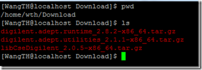
    As I installed ubuntu 11.10 x64 on my laptop, the packages I have are shown in the figure below:

    0003

    Decompress all packages with command “tar zxvf <filenames>”

    0004

2. Install Digilent Adept Runtime 2.8.2

     Enter directory digilent.adept.runtime_2.8.2-<platform>

     run command “$ sudo ./install.sh” and keep all default locations unchanged.

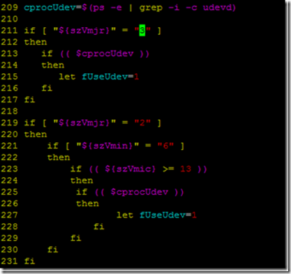
     * NOTE: If you are install on Ubuntu 11.10 or other recent distributions with kernel version >= 3.0 (verify it with command `uname –r`)
                      You need to add the following lines after line 209: cprocUdev=$ (ps –e | grep –I –c udevd)

209 cprocUdev=$(ps -e | grep -i -c udevd) 
210 
211 if [ "${szVmjr}" = "3" ] 
212 then 
213        if (( $cprocUdev )) 
214        then 
215               let fUseUdev=1 
216        fi 
217 fi

                      0005

     Here is the log:

[WangTH@localhost digilent.adept.runtime_2.8.2-x86_64]$ sudo ./install.sh
Adept Runtime Installer
64-bit operating system detected
In which directory should libraries be installed? [/usr/local/lib64/digilent/adept]
Installing runtime libraries…..
Successfully installed runtime libraries.
Installing system binaries…..
    installed "/usr/local/sbin/dftdrvdtch"
Successfully installed system binaries in "/usr/local/sbin".
Installing firmware images…..
Successfully installed firmware images in "/usr/local/share/digilent/data/firmware".
Installing JTSC device list…..
Successfully installed JTSC device list "/usr/local/share/digilent/data/jtscdvclist.txt".
Installing CoolRunner support files…..
Successfully installed CoolRunner support files in "/usr/local/share/digilent/data/xpla3".
Installing CoolRunner 2 support files…..
Successfully installed CoolRunner 2 support files in "/usr/local/share/digilent/data/xbr".
Installing Adept Runtime configuration…..
Successfully installed Adept Runtime configuration "/etc/digilent-adept.conf".
Installing USB UDEV rules…..
Successfully installed USB UDEV rules "/etc/udev/rules.d/52-digilent-usb.rules".
Installing dynamic loader configuration…..
Successfully installed dynamic loader configuration "/etc/ld.so.conf.d/digilent-adept-libraries.conf".
Successfully reloaded UDEV rules.

[WangTH@localhost digilent.adept.runtime_2.8.2-x86_64]$

3. Install Digilent Adept Utilities 2.8.2

     Enter directory digilent.adept.utilities_2.8.2-<platform>

     run command “$ sudo ./install.sh” and keep all default locations unchanged.

     Here is the installation log:

[WangTH@localhost digilent.adept.utilities_2.1.1-x86_64]$ sudo ./install.sh
[sudo] password for WangTH:
Adept Utilities Installer
64-bit operating system detected
In which directory should binaries be installed? [/usr/bin]
In which directory should manuals be installed? [/usr/local/man]
Installing binaries…..
    installed dadutil: "/usr/bin/dadutil"
    installed djtgcfg: "/usr/bin/djtgcfg"
Successfully installed binaries in "/usr/bin"
Installing manuals…..
    installed dadutil.1: "/usr/local/man/man1/dadutil.1"
    installed djtgcfg.1: "/usr/local/man/man1/djtgcfg.1"
Successfully installed manuals in "/usr/local/man"
Successfully installed Adept Utilities

4. Install Digilent Plugin for Xilinx Design Suites

    Enter directory libCseDigilent_2.0.5-<platform>

    Enter directory of the Xilinx DS version installed on your computer.

    For me, it was ISE13x, because I installed Xilinx DS 13.2

    There is a pdf under the folder named: Digilent_Plug-in_Xilinx_<versionNo>.pdf

    The document tells exactly how to install the Digilent Plugin and how to use it.

     To install plugin is quite easy, all you need to do is copy the libCseDigilent.so and libCseDigilent.xml to

     <Xilinx_DS_Path>/ISE/lib/lin64/plugins/Digilent/libCseDigilent/  (if 64-bit OS)

    or <Xilinx_DS_Path>/ISE/lib/lin/plugins/Digilent/libCseDigilent/ (if 32-bit OS)

    if there is no dir “Digilent” under <Xilinx_DS_Path>/ISE/lib/lin64/plugins/, just make a new dir with command mkdir.

    On my computer:

0006

Section III: Test and Troubleshoot

1. Connect your digilent board to your PC

     Test whether Adept utilities can recognize your board.

     All you need is to run the command “djtgcfg enum” and see whether your boards pop up.

2. Open iMPACT with command “impact&”

     See if any FPGA can be found on your JTAG chain.

(I will go on with this part later, good luck Smile with tongue out)

Embedded Linux – Memory Management Line by line [1]– Intro to MMU

For embedded system, memory management varies from system to system, as you have your custom address space and custom peripheral devices and memory chips. Sometime, the porting of kernel may fail if the memory management is not carefully handled.

Years ago, uclinux was well-known as a linux operating system without MMU, which is more suitable for embedded systems back at that time. As FPGA has become more and more powerful, embedded OS can support MMU now. And for Linux running on Xilinx FPGA with microblaze or PPC, the MMU is required, as said in the documentation.

In this blog series, I am going to tell the story about memory management of Linux OS line by line. The story begins by introducing the MMU of microblaze.

MMU of Microblaze on Xilinx FPGA\

Memory Management Unit (MMU) is a piece of hardware, which bonded closely with CPU (microblaze/PPC here) to provide memory management functionality for softwares, especially operating systems.

MMU can function in two modes:

1. Real Mode: effective address are used to access physical memory directly.

2. Virtual Mode: effective address are translated into physical address to access physical memory by the virtual-memory management hardware in microblaze.

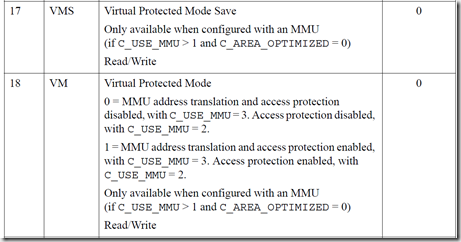
The mode is controlled by the 18th bit (VM) of rmsr (Machine Status Register), as shown in fig. 1.

image

                                 fig. 1 Machine Status Register

image

At the very beginning, the MMU runs in real mode, as the reset value of VM is 0. After OS properly set the first several entry in TLB (Translation Look-aside Buffer), the MMU will switch into Virtual Mode.

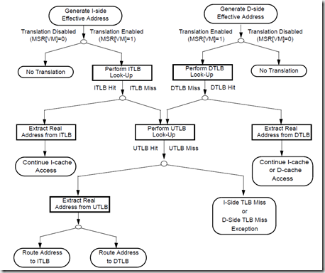
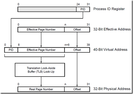
In virtual mode, whenever an address is requested, it goes through the following procedure:

image

To understand this procedure, we need to know so-called Translation Look-aside Buffer (TLB). TLB can be viewed as a cache for address translation. The translation between virtual address and physical address in virtual mode is done via a kind of mechanism called 2-level page table translation. In microblaze, the translation goes as follows:

image

There are certain addresses that are frequently accessed, the translation is stored in TLB, the same we do for data cache. If the requested data is not found in TLB, a TLB miss (similar as cache miss) is generated, followed by the page table translation and TLB update operation.

There are four registers used for accessing TLB from software: TLBLO, TLBHI, TLBX, and TLBSX.

TLBLO: Translation Look-Aside Buffer Low Register

TLBHI: Translation Look-Aside Buffer High Register

TLBX: Translation Look-Aside Buffer Index Register

TLBSX: Translation Look-Aside Buffer Search Index Register

All these registers are accessed via MFS and MTS instructions.

Access TLB Entries

First of all, we need to know the TLB entry structure. A TLB entry can be accessed via TLBLO and TLBHI registers, with an index set at TLBX.

image

RPN (Real Page Number or Physical Page Number) is used to form physical address. Depending on the value of page size, certain bits of RPN are not used in physical address.

TAG (TLB-entry tag) is compared with the virtual memory address under control of SIZE.

SIZE (page Size) specifies page size.

There are 64 entries in the unified TLB in microblaze MMU architecture. So the INDEX field (bit 26 to 31, as shown below) of TLBX register is used as index of MMU entries. The field is also updated when TLBSX register is written with a virtual address and the virtual address is found in TLB entries.

image

Software can read and write unified TLB entries by using the TLBX register index (numbered 0 to 63) corresponding to one of the 64 entries in the TLB. The tag and data portions are read and written separately, so software must execute two MFS or MTS instructions to completely access an entry. The TLB is searched for a specific translation using the TLBSX register. TLBSX locates a translation using an effective address and loads the corresponding UTLB index into the TLBX register.

Conclusion

All the above are the story about MMU architecture of microblaze. You may refer to xilinx document: MicroBlaze Processor Reference Guide for more detail explanation on microblaze and its instructions. The figures and information in this blog comes from the document directly. Linux kernel set up memory page mapping in arch/microblaze/head.S. I am going to talk about the codes in head.S in next blog in this series.

WordPress Tags: physical address,virtual address,TLB,Xilinx,FPGA,microblaze,MMU,Linux,Memory Management

what you need to Run Linux on XILINX FPGA

To run a kernel on a piece of hardware, you need several tools and a stable environment to do your job in.
Here is my tool lists, with a hyperlink so that you may easy to download them and repeat my job


Environment

Let’s just begin with environment.
I recommend doing your entire job in Linux OS. To compile a linux kernel in a linux environment is the safest way to do, and fastest.
There are plenty of distributions for Linux out there for you to choose.
According to my experience with different distributions, here is my recommendation:

1. RHEL/CentOS 5.x or 6.x

Although in different names, RHEL (RedHat Enterprise Linux) and CentOS are basically the same. They share same rpm repositories, same kernel version, just named differently.
It is the environment that is most stable and hardly ever goes wrong. It may be a little bit slow to run on your laptop, but it’s the first choice for a beginner.

2. Ubuntu

I know a lot of people who are fond of Ubuntu, because of its glorious desktop. As more and more people are switching to it, it has a great support community on-line. You can easily find any solution to your problem. If you want a linux system on your personal laptop, it will be a good choice.

3. Debian

For people who have experience with Linux, I would like to recommend Debian. I am personally fond of Debian, because of its speed in compilation. Debian is the fastest system for software compilation. It takes one thirds time to compile a kernel than Fedora. However, as not many people work on it, you may need to solve your problems alone. So, if you are a linux guru, pick this one
Another important thing to mention is that you’d better have enough space to build your kernel source. Xilinx Tools may cost you about 10GB of your file system and the kernel source folder after compilation will cost 1GB. When you have more than one kernel sources in your system… that’s quite a lot space…


Tool Chain

There is a saying that if you want to do a job right, you need to find proper tools. Here is what you need to build kernel on your FPGA board.

1. Xilinx Design Suite

That’s definitely what you need to build up an microblaze system on your FPGA and that’s the piece of hardware you will run you kernel on.
The version of Xilinx DS I recommended currently are 12.4 or 13.2.
It can be downloaded from http://www.xilinx.com
Well, I have to say, the installation package gets bigger and bigger these days… You’d better have enough space for that.

2. Cross-compilation Tool Chain

As you are going to compile linux kernel for Xilinx Microblaze instead Intel CPU, you need a cross-platform compilation tool chain to do the work for you. The reason that they are named “cross-compilation” is that they themselves run on x86 or x64 systems while their output binaries run on other platforms.
For cross-compilation tool chain we use here, there are two places you may get them:

a> ${XILINX_DS_DIR}/EDK/gnu/microblaze/lin(64)/bin/mb-*
These gnu compilation collection work for microblaze (Big-Endian) by default. If your design is an AXI based system, you need to add –mlittle-endian to compilation flags and –EL to link flags.

b> They are available at http://git.xilinx.com
You may download and compile them for your own system.

3. Kernel Resource

Actually, xilinx open source wiki keeps a neat and clean tree for linux kernel. the source files can be download at: http://git.xilinx.com
For details, you may refer to xilinx open source wiki at http://xilinx.wikidot.com

4. Device Tree

To make your kernel know about your hardware, especially how the virtual memory of CPU are organized and which part of physical memory each peripheral device locates at, you need device tree to get all these information for kernel. The device tree for Xilinx EDK is available at: http://git.xilinx.com . It will generate a dts file for your hardware automatically and checks out the necessary peripheral devices necessary for linux kernel.


Requirement on Hardware

For the hard ware system you want to run linux on, here are a set of things you have to instantiate in your design:

1> a memory over 10 MBytes.

You need space to hold kernel image and stacks for processes. However, I am still checking on the exactly minimum size of memory needed.

2> Interrupt controller

You definitely need this. This is how OS interface with outside world and avoids busy waiting.

3> Timer

Without timer, OS cannot do scheduling.

4> Uart

This is the easiest way to interact with your kernel, and see what’s going on.

5> you may add other ip cores you want or your custom ones.

Besides all these peripherals, you also need to configure microblaze.

1> Enable MMU

In early days, embedded linux system always claim that a kernel without MMU is its advantage, as it runs fast and works tight with hardware registers underneath. However, as embedded systems run faster, embedded OS’s are able to provide better memory management functionalities to user processes. As stated clearly on xilinx open source wiki, MMU is required with 2 protection zones available.

2> cache

cache is needed for synchronous SRAM or SDRAM to make the system run faster.

3> FPU, MULT, SHIFT, etc.

add and configure as you like. Certainly, they can be helpful.

After settle down all these, you can begin to build your kernel for your hardware now.


WordPress Tags: Cross-Compilation,device tree,Linux,XILINX,FPGA,kernel,Microblaze,Hardware

How-To Debug Linux Kernel with Xilinx FPGA

To compile and successfully boot an operating on a piece of hardware is an interesting job. Anyone who is interested in understanding how a computer system work will always find it fascinating to run a full OS kernel on a hardware that you create yourself.

Back to the days when I studied linux kernel in my senior years, the first thing I got to do is to compile a linux kernel on your own laptop. It is very likely that the kernel panics during the boot sequence. Well, as it is the kernel, you have no way to debug but reboot your computer, browse through the internet to see which configuration you missed or misconfigured, reconfigure the kernel, and wait another hour to get it recompiled.

These days, I am trying to run linux kernel on Digilent Atlys FPGA boards (with Xilinx Spartan6 LX45 FPGA on it). With the help of Xilinx Design Suites and the kernel maintained at http://git.xilinx.com. It will be easy to do debug for Linux kernel and understand how the kernel works.

Here is the procedure to follow to debug linux kernel on Xilinx FPGAs:

Ø Start two Xilinx Bash shell. One as a debug port that downloading linux image onto Atlys, while the other as the gdb debugging interface.

Ø Browse to where your linux kernel is located. run xmd.
Connect to atlys board by typing:

% connect mb mdm -cable type xilinx_plugin modulename digilent_plugin

Note: A GDB server will open on localhost:1234 with tcp protocol.

clip_image001[3]

Ø Dowload the kernel image onto FPGA

% dow simpleImage.Atlys_mmu

clip_image002[3]

Ø In the other Xilinx bash shell, go to the root directory of the kernel you built.
Launch mb-gdb by

% mb-gdb -nw vmlinux

clip_image003[3]

Ø Connect to localhost:1234 for remote debug.

(gdb) target remote localhost:1234

clip_image004[3]

Now we have set up the debugging tool chane for Linux Debugging on FPGA.


WordPress Tags: MMU,Debug,Linux,Kernel,Xilinx,FPGA,Digilent,Atlys,Microblaze

SUMMARY OF CTEX LEARNING -- CTEX小结(.cls与.sty文件的编写)

1. How to write .cls & .sty file:

1.1 Difference between CLASS file and STYLE file in CTEX:

Class file (.cls) is used to define document classes with definitions of page margin, document style, and various options that user can pass to the class to configure the structure of this kind of document. For instance, the built-in classes include article, book, report, etc.

Style file (.sty) is used to define a kind of style, such as the font and size of book title, title of each section and subsection, the space between lines.

The golden rule you should obey to decide whether it should be a class or a style goes as follows:

If the commands could be used with any document class, then make
them a package; and if not, then make them a class.
— Quoted from book: LATEX2E FOR CLASS AND PACKAGE WRITERS

1.2 How to write a CLASS

The class file composed of mainly four sections: Identification, Resources Required, Option Declaration, and Style definition.

1.2.1 Identification

Identification is used as an ID for the class you are about to compose.
the very command used here is:
\ProvidesPackage {package_name} [<date> <introduction>]

e.g. \ProvidesPackage{digilentTrans}[2010/06/09 Translation Template]

1.2.2 Load a Package

We can use function “\RequirePackage” to load a style package or use “\LoadClass” to load a class file.
\documentclass is also available here, so that we can refer to external files for document properties.

1.2.3 Option Declaration

It is recommended to use function “\DeclareOption [option_name] {function}”
Here, we can specify the function when certain option is passed to this class. Moreover, we may pass the option to the class package we are about to load. The function “\PassOptionsToClass” helps in this situation.

We may use \DeclareOption* to define the default behavior when certain option is passed onto this class.

1.2.4 Style Definition

Style definition usually means define or redefine a series of macros to modify the character, paragraph, document attributes. We may redefine “\title” function to change the position, font, style, size, color, etc. of the title.

If the command is new, it is recommended to use “\newcommand [command_name] [<num>] {function}”
where <num> is the number of parameters the command can take. In “function” part, “#1” stands for the first variable, “#2” the second, and so on. if the command has been defined in the package included or by default, we should use \renewcommand. If we want to access the old command in renewed command, we should write “\gdef \@command_name \par”

2. Problems concerning Chinese characters in CTEX

2.1 Commands of CTEX

CTeX is the package that support Chinese characters. You may type “$ ctex” under command line to see the options.

It is better to use “-pdflatexmx” while using chinese characters, as italic style is not available for chinese characters if you use other options.

2.2 Chinese Characters

CTeX includes a package for chinese characters called “CJK”. There are other packages for Chinese characters, while CJK is the one commonly used and is default in CTeX classes.

To use a CJK package, you should first include CJK in your .tex file as follows:
\include {CJK}

To use CJK font in document, before the text you may write:
\begin {CJK*} {GBK} {song}

This command stands for using CJK package GBK character map, font SongTi.
in GBK, the following fonts are available: song – SongTi, hei – HeiTi, kai – KaiTi, fs – FangSong.

We can use GB instead of BGK. Here we have more fonts:
gcfang – FangSong, gckai – KaiTi, gchei – HeiTi, gcsong – SongTi, gcwei – WeiBei, gchw – ZongYi, gcdls – LiShu.

\bfseries stands for bold style, \textsl stands for italic style.

2.3 CTEX classes

CTEX provides several document classes that support Chinese Language. ctexart is the article class with chinese support, ctexbook is the book class with Chinese support, ctexreport is the report class with chinese support. It is more convenient to use these classes while writing chinese documents. the reference for CTeX can be found at
http://ctex-kit.googlecode.com/files/ctex.pdf

(Please include a link to this page while coping this article to other website or forum, Thanks!)


破窑赋 [吕蒙正]

天有不测风云,人有旦夕祸福。
蜈蚣百足,行不及蛇;
家鸡翼大,飞不如鸟。
马有千里之程,无人不能自往。
人有凌云之志,非运不能腾达。

文章盖世,孔子尚困于陈邦。
武略超群,太公垂钓于渭水。
盗跖年长,不是善良之辈。
颜回命短,实非凶恶之徒。
尧舜至圣,却生不肖之子。
瞽叟顽呆,反生大圣之儿。
张良原是布衣,
萧何称谓县吏。
晏子身无五尺,封为齐国首相。
孔明居卧草庐,能作蜀汉军师。
韩信无缚鸡之力,封为汉朝大将。
冯唐有安邦之志,到老半官无封。
李广有射虎之威,终身不第。
楚王虽雄,难免乌江自刎;
汉王虽弱,却有河山万里。
满腹经纶,白发不第;
才疏学浅,少年登科。

有先富而后贫,有先贫而后富。
蛟龙未遇,潜身于鱼虾之间。
君子失时,拱手于小人之下。
天不得时,日月无光;
地不得时,草木不长;
水不得时,风浪不平;
人不得时,利运不通。

昔时也,余在洛阳,日投僧院,夜宿寒窑。
布衣不能遮其体,淡粥不能充其饥。
上人憎,下人厌,皆言余之贱也!

余曰:非吾贱也,乃时也,运也,命也。

余及第登科,官至极品,位列三公,
有挞百僚之杖,有斩鄙吝之剑,
出则壮士执鞭,入则佳人捧秧,
思衣则有绫罗锦缎,
思食则有山珍海味,
上人宠,下人拥,
人皆仰慕,言余之贵也!

余曰:非吾贵也,乃时也,运也,命也。

盖人生在世,富贵不可捧,贫贱不可欺,
此乃天地循环,终而复始者也。

《写在人生边上》

最近为了交20世纪名著选讲这门通选课的文章,一直埋首于钱钟书的这本“写在人生边上”之中。
钱先生的围城记得在中学课外阅读的书目上出现过,不过过去没去读什么……
最近读了钱先的这本很薄的集子,不禁有不少感触,便想把它放在这个空间上,以兹大家分享。
也请读了的朋友多多少少留些痕迹下来,在此先谢了。